LED Pinball Display For Early Bally/Stern Games
Author: Wayne Eggert
Date: 08/14/2011
Introduction
I've been working on prototyping an LED display for early Bally/Stern pinball machines. There are commercially available pinball displays for these machines readily available, but at a pretty steep price point. So since I'm interested in learning how the displays work, I decided to make it a project =)
Initial Prototype
This has been several months in the making, originally I was prototyping
entirely on a breadboard and only hooked up two digits due to a MESS of
wires. I was using common anode LED digits with the digit enable transistors hooked up in an emitter-follower circucit that would have in theory minimized the amount of components neede. It was not working correctly -- as the number of segments lit changed, the segments would either dim slightly or be slightly brighter. I'm thinking the emitter-follower circuit was too dependent on the current gain (that's what a transistor does, it takes a small current at its input and amplifies it at the output). Anyway, I ordered some common cathode LED digits so I could try prototyping a different circuit.
Digit Display Board
I worked on the digit display board first. As the name suggests, this is just a board with the display digits. On the old Bally/Stern games the displays were hooked into the display boards at a 90 degree angle and the display board then slid into a metal chassis. Anyway, this board was an important first step because it will be the first time I will have had all 6 digits wired up and ready to test.
Wiring it was a mess -- each digit needed to have its segments connected to the next digit. But such is the nature of prototyping. The end result is a pinout for the 7 segments and a decimal point and separate pins to enable each digit. This board will connect into the component board that will have all the ICs, transistors, resistors, etc needed to interpret the signals from the pinball MPU board.
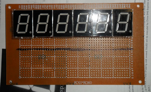
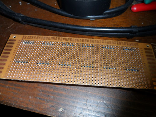
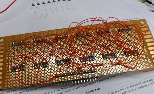
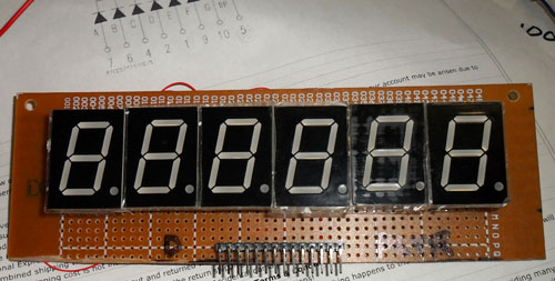
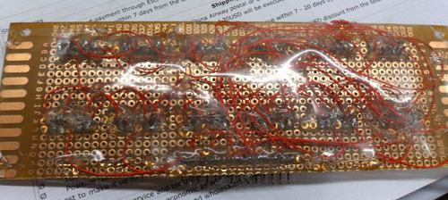
Picture: Hot Glued over all solder points and then put a thin sheet of plastic over entire back
Component Board
The next thing to work on was the component board / display driver circuitry. This circuitry would need to mimick what the components on a factory Bally/Stern display are doing. This means taking the BCD (binary coded decimal) data, player latch, blanking input line and digit lines -- and interpreting all of these signals to output to the LED displays.
I used a breadboard to prototype this part of the design because it made it far easier to make changes as I was figuring out the design.
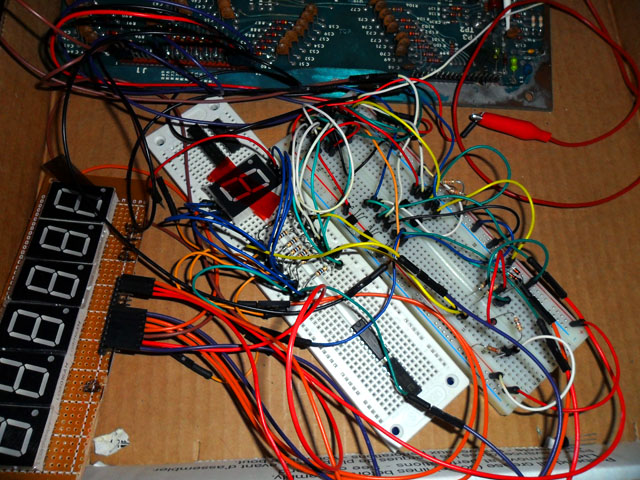
Picture: Display Driver Circuitry on Breadboard
I learned quite a bit about using transistors as switches while working on this part of the design. At one point I had hooked up the transistors in an emitter-follower circuit and the LED brightness would depend on the input voltage. This was causing issues -- as more digits were added, the led's dimmed slightly. Instead, hooking the transistors up in a common-collector configuration eliminates dependency on input voltage of the transistor & allows the transistor to work like an on/off switch.
Slight Change of Direction
I had this "mess of wires" sitting in a box lid for over a year. I had a schematic drawn up & board layout ready to go -- but found out the boards would be too costly to prototype & didn't feel the design was 100% yet. Initially I was going to make full-size replacement displays for a machine. This means larger board size due to larger LED digits being used & also needing the boards to be a similar size as the factory displays so they fit into the display holders on the machine. This also meant having a design that would be as low power consumption as possible. There was going to be a lot more work needed -- possibly switching over to mosfets instead of transistors.
In early March 2013, I decided to change directions slightly with this project. Instead of shooting for full-size replacement displays for Bally/Stern machines, I decided to instead shrink the design down to as small of a board layout as possible & add some microswitches to switch between the various player displays. This would make it an effective bench testing display for people that repair these MPU boards & also allow me to wrap-up the work I had done thus far (and finally get rid of that box lid mess of wires!). So.. I redesigned the board, and had some prototypes made up..
Introducing the Bally/Stern Bench LED Display
Finally the result of many months of work on this project -- a fully working LED display that can be used at the bench or be hooked up in a classic Bally/Stern machine to verify display circuitry on the MPU is working. The momentary buttons allow you to switch between players or the credit/match display easily. This prototype is pretty compact -- about 4in x 1.5in in size. The display digit board is stacked on top of the component board. I think it turned out pretty slick! For more information, check out the Bally/Stern Bench LED Display at Pinitech!
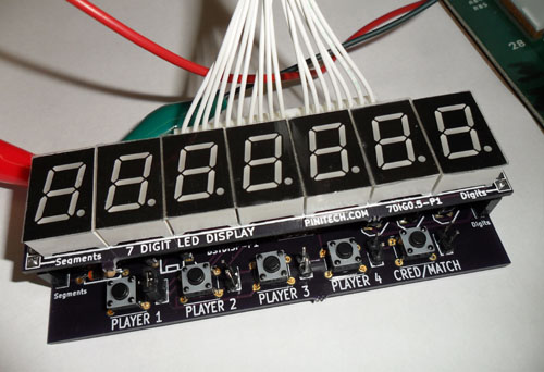
Picture: Bally/Stern Bench LED Display
Comments:
| Re: Any progress? |
| Posted 02/25/13 5:08PM by AceBHound |
| Yes, I got much further toward the end of 2011 and have had this project sitting on a breadboard since early 2012. The display is fully working -- lots of wires :) But I also designed the board layout for this and was going to have some prototype PCBs made.. but kept tweaking the design and finally decided to hold off on having prototype PCBs made until I have some other designs I throw into the same panel. I don't think the design is anywhere near done.. I already have changed around ICs and components used many times -- but it'd still be nice to have actual circuit boards made up even for how things stand currently. Anyway great project if you want to learn a little something about how displays in pinball machines work. |
| Any progress? |
| Posted 12/14/12 2:02AM by BrianHanifin |
| Have you gotten any further on this project? I am intrigued by this project. I agree it could be fun to build your own display board. :-) |
| sliding led |
| Posted 12/14/11 4:39AM by dattatry |
|
try this new led parts:2 capacitors value:10v,25uf 4 rasistance value:2k ohm,2transistor 545 |
