Using a Logic Probe
A Few Words of Caution
Logic probes are only used to
analyze "digital logic", which means the signal is either "ON" (+5v) or
"OFF" (+0v). A few words of caution are necessary at this point because
you have to understand that a logic probe isn't the end-all be-all to
repairing something. In fact, if you don't know what you're probing or
if you accidentally short two IC pins together you could do harm to a
circuit board or possibly cause personal injury. Be mindful of what
you're probing.
So back to the two alligator clips. The red alligator clip hooks to +5v of your circuit. DO NOT, I repeat DO NOT hook up the red alligator clip to voltage higher than +15v.. nothing good will come of that. Usually logic probes are used to analyze 5v circuits and that's what this tutorial will cover.
Briefing on Digital Logic
Okay lets talk digital logic
again. 01001010010011101101101. Got it? Sorry, I apologize for that
unecessary bit of nerdy humor. Actually all those 0's and 1's are
exactly what digital logic is. You may have heard that at its core,
your computer is running on 0s and 1s. Well it's completely true! As
you're browsing this web page right now your computer is spitting out 0s
and 1s all over the place -- when you move your mouse, when you scroll
the page down, when you get an instant message from your friend telling
you to stop being nerdy and go outside. It's all 0s and 1s, it just
looks prettier cause we can't all see the 0s and 1s like in The Matrix.
The interfaces are "dumbed down" so us simpletons can watch slideshows
of LOLCats while listening to Ted Nugent's Cat Scratch Fever and bask in
the glorious eye candy of it all.
What's actually happening though is a bunch of 0s and 1s are being sent out and interpreted by various hardware inside your computer or CPU-based circuit board. These 0s and 1s are called "digital logic" because the signal is either ON or OFF -- HIGH (5v) or LOW (0V).
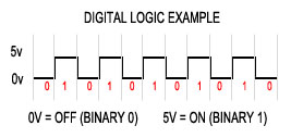
An example of digital logic is below. A string of 0s and 1s can be sent "digitally" by varying the voltage from 0v to 5v. Maybe those 0s and 1s represent your email or pictures uploading off of your USB-based camera, or the resume you send to your printer.

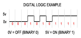
Don't be fooled by the consistent pattern of 0s and 1s above, this could just as easily look quite different depending what data is being sent as in the example below.

All of this is happening at an insanely fast rate, if it didn't happen fast there would be no way your computer could be drawing graphics to the screen while playing a music cd and interpreting your mouse clicks.
All of these 0s and 1s are coordinated with a "clock signal". The clock signal gives the data being sent (all those 0s and 1s) a timing reference. Think of the clock signal like a metronome (if you're familiar with music), wall clock, egg timer or stopwatch. They're all ways to reference time and help us to determine if we're playing musical notes too fast, if we're on-time or late for an appointment, if we've underbaked or overbaked something or if we shaved 30 seconds off our best 5 mile run. A clock signal helps the computer determine at what point to capture a signal to determine if it's a 0 (LOW) or 1 (HIGH).

Above you can see a clock signal / pulse which is also a square wave. It has a 50% duty cycle meaning it's ON time is the same as it's OFF time. The clock doesn't typically change while the circuit is running.. it's rather boring in that sense and likes to be consistent. Actually it's a good thing that it's boring, otherwise nothing would work right. The clock signal is basically the heartbeat of digital electronics and if the timing wasn't always consistent then all those 0s and 1s would be completely useless. By having a consistent clock, the CPU knows when to check for a signal of 0v or 5v.. or it knows that after a certain amount of clock cycles (pulses) that it should have received all the data being transmitted.
Ever hear of someone "over-clocking" their computer? Or ever try to run a really old DOS program that ran TOO FAST on a new computer? Those things all have to do with the clock signal. The faster the clock signal (ie. 3mhz is MUCH slower than 3ghz) the faster those 0s and 1s can be transmitted and interpreted by the CPU.
And that was probably more than you ever wanted to know about digital logic! But it's important to understand just what the heck you're trying to "see" with the logic probe anyway.. and what you're trying to see is the 0s and 1s (0v or 5v) being transmitted. That way you can find a "STUCK" input or output and isolate the bad component while the circuit is running.
page1 page2 page3 page4Comments:
| Re: Great article. |
| Posted 09/30/12 10:55AM by AceBHound |
| Thanks for pointing out the spelling mistake! Always happy to fix any of those cause they drive me nuts too =) |
| Great article. |
| Posted 09/27/12 5:01PM by Anonymous Techdoser |
| Great article. Just one small nit-picking point. On page two, you use the word "here" when you mean "hear". Sorry about that. I saw this mistake made twice today. |
