How to Use Solderless Breadboards

How Do Breadboards Work?
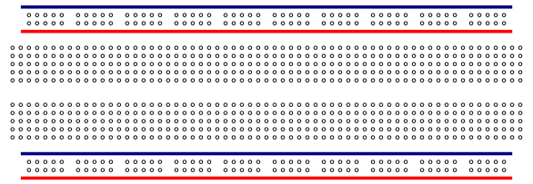
Solderless breadboards have rows of tie points that are electrically connected to eachother at various points. Try hovering over the image above to see where these tie points are electrically connected (in green). You'll probably want a breadboard "power rails" as in the picture above, as this makes it easier to tie into your power source. The tie points in the rails are connected the entire length of the rail and allow you to connect a power source to a single point on the rail and have access to the power at any other tie point on that rail. Many breadboards mark these rails with red and blue lines to show the tie points are connected the entire length of the rail. You can use the rails however you wish (ie. connect 5v power positive & ground to the left side, or 5v positive to the left and the negative to the ground, or 5v power/ground to one side and 3.3v power/ground to the other side).
In the middle of the breadboard there are two rows of 5 tie points that are connected electrically (again, hover over the breadboard above to see this). You don't want to put all of a components leads into a single row of 5 tie points since they're electrically connected together and you would be creating a short circuit. Instead, you connect one lead of a component to one row of tie points and the other lead(s) to different rows of 5 tie points so they're electrically separated.
Using the tie points you can create circuits on the breadboard, but you must know how these tie points are connected electrically so you don't short-circuit something. A breadboard does not tell you whether you hooked something up incorrectly, but if you're not using some caution the smoke coming from the component will help you figure that out!
Let's Hook Up Something
A while back I wrote a basic electronic tutorial on how to wire up a simple LED. We'll be creating that circuit on the breadboard, so if you haven't already, view the simple LED tutorial before going any further. Now that that's out of the way, lets wire it up!
Here's the non-technical picture of the circuit we'll beuild on the breadboard:

Step 1: Connecting the Power Source
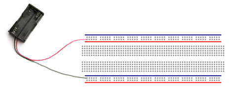
You're going to need a DC power source of around 3v or more. I used a battery holder with 4 AA 1.5v batteries. This created a 6v power source. You can use a 9v battery or a 3v battery source, whatever you have available, however the requirements of the resistor in the circuit may change depending on the battery source you're using. So that's why it's important to read the simple LED tutorial to find the resistor value you'll need.

Next we'll start connecting components..
page1 page2
page3 page4 page5 Comments:
| Nice |
|
Posted 03/22/12 4:44PM by Anonymous Techdoser
|
|
Now where do you buy them? I found an interesting place to buy them at nordevx.com Anybody know of some other places? |
| anonymous techdoser |
|
Posted 01/22/12 2:44AM by Anonymous Techdoser
|
|
i did this and blowed an led! |
| Internal Connection of Breadboards |
|
Posted 12/17/11 10:55AM by ashoksharmaz87
|
The article is really very good!
Another good link that I found about breadboard is http://www.engineersgarage.com/insight/how-breadboard-works
|
| Short circuit? |
|
Posted 10/16/11 4:34AM by Anonymous Techdoser
|
|
Hi, can anyone please explain why putting both the LED leads into holes which are electrically common would create a short circuit? I'd say there would just be no potential difference across the LED, hence it wouldn't light up. Am I wrong? |
| switch |
|
Posted 04/23/11 1:22PM by Anonymous Techdoser
|
|
hello can anyone please help me find out how to connect a switch with the board? Thanks. |
| attach a switch |
|
Posted 02/23/11 8:11PM by Anonymous Techdoser
|
|
how can I connect a six pin right angle slide switch to this set up |
| Thanks |
|
Posted 01/05/11 12:09AM by Anonymous Techdoser
|
|
This is a clear explantion for anybody tryuing tono about solderlessbreadboard. Thanks a lot |
| bread board |
|
Posted 10/28/10 8:56AM by ragraghu_k
|
very good for the learners , its climbing the ladder step by step , i think i can learn a lot
thank you very much |
| thanks |
|
Posted 10/18/10 6:41PM by dvdove
|
|
good info,easily understood. |
| Diagram error |
|
Posted 09/23/10 7:35PM by Anonymous Techdoser
|
|
In the diagram showing the LED connection to the battery, the resistor needs to be connected between the positive lead of the battery and the LED. The diagram is shown backwards, therefore, the voltage will be too much and probably blow the LED. |
| Thx |
|
Posted 08/01/10 12:52AM by Anonymous Techdoser
|
|
Simple but Useful...:D |
| Hello! |
|
Posted 10/31/09 12:01PM by RikiKiki
|
|
You've made my day! Very useful! |
| Thanks for this great site |
|
Posted 10/27/09 3:28PM by Voiseriaffona
|
Thanks for the information
This is a very great site. I am bookmarking it soon |
| You have a good site www.techdose.com all very tastefully done! |
|
Posted 10/02/09 6:27AM by rittachkas
|
You have a good site all very tastefully done! I really liked.
Sincerely Ritt. |
| Breadboards - How to... |
|
Posted 09/26/09 10:36AM by Anonymous Techdoser
|
|
Superb!!! As an electronics novice I'm very thankful for your informative intro...Cheers |


