Repairing an Electrical Plug With Ground Pin Cut Off
Tools / Materials Needed
- 125v / 15A Grounding Plug With Clamp (Leviton 515PA, 515PV or similar)
- Phillips Head Screwdriver
- Flat Head Screwdriver
- Wire Cutter
- Multimeter (to verify wires)
The New Plug / Adapter
Lets first take a look at the new plug adapter. I bought a few Leviton 515PV's off of Amazon. The cheapest I could find them for at the time was about $2.75 each. They are rated 125v 15 Amp, so are suitable for pinball machines or most other normal 120v household appliances.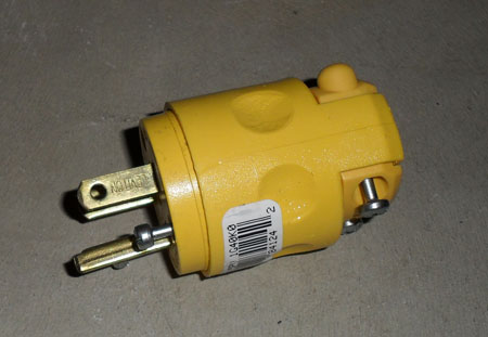
Picture: New Leviton 515PV Grounding Plug
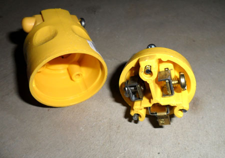
Picture: Inside the New Plug
The picture above shows the screw terminal hook-ups for the new plug. Notice that when inserted back into the plug housing, each wire would be in a separate compartment and isolated from the other wires.

Picture: Plug Terminal in Detail. Ridges and embossed area help grip the wire.
I wanted to take a closer look at the terminal so I used a flat head screwdriver to remove the screw completely. Normally in these terminal arrangements you're just supposed to insert the wire straight-on and tighten the screw to clamp down on the wire. You can see that there are ridges on the blades of the plug & also the clamp has a raised area -- both of these help to grip the wire and prevent it from pulling out. I'm not fully trusting of this and would prefer to wrap the wire around the screw, but it is what it is. In this case it would be difficult to remove the screw completely, wrap the wire around it, then insert the screw and clamp again -- so we'll just use it as it was designed.
Repairing The Plug
Step 1: Unplug The Cord!!
First step is easy, unplug the cord from the outlet. It may seem trivial enough, but if I don't say it then someone out there is going to cut the cord while it's connected and not be happy with the results.
Step 2: Cut Off The Old Plug
Next of course, you'll want to cut the old plug off using large wire cutters. If you're unsure of which wires are hot/neutral (if they are not color coded or you want to verify) you should leave a little excess cord on the plug so you can verify the wires. It's probably a good idea to just verify the wires even if you think you know.
In my case, there was a ribbed texture on one side of the wire, usually indicating the neutral / common wire. I could also assume that it matched up with the left blade/prong of the plug, but we'll verify that with a continuity test just to be sure. Some grounded wires just have round insulation and do not have any marking for the neutral wire. Usually the wires will be individual colored (black = hot, white = neutral, green = ground) inside the insulation. Again, you can use the continuity on a multimeter to verify the wires.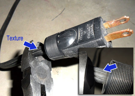
Picture: Texture on wire indicates neutral/common wire (could also be writing, etc)
Step 3: Verify Neutral, Hot & Ground Wires
This step is important even if you think you know. Better to be safe than shocked! =) You'll want to use a continuity test on your multimeter to verify which wires correspond to neutral, hot and ground.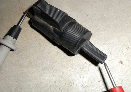
Picture: Continuity Test to Verify Wires
In the picture above, I'm testing the hot wire (opposite side of the textured wire). The plug is upside down, so I'm actually testing the right-prong that should correspond to the outlet's "hot" wire slot. The black multimeter lead is on the right-prong since when inserted into an electrical outlet, the right-prong (and right slot on the outlet) is the "hot". The textured side corresponds to the left slot on the outlet, or "neutral".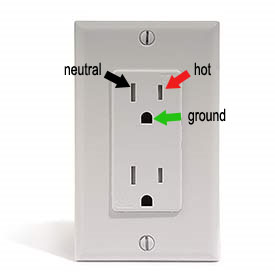
Step 4: Separate the Wires
Next separate the wires. You will most likely have to use the wire cutters again here to start separating the wires. The insulation can make this a little tough (which is a good thing), so you may need to first cut a starting point and then use pliers to separate the wires fully. On a round wire you'd need to strip back the insulation but the wires themselves are most likely all insulated with correctly colored insulation material.
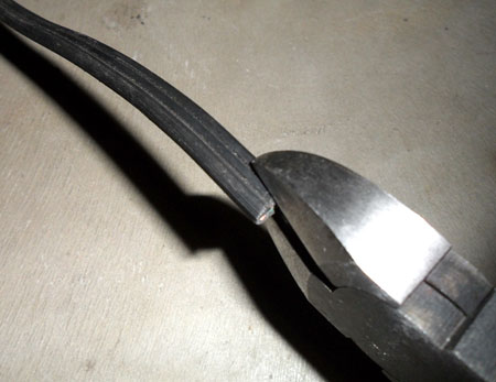
Picture: Making Initial Cut to Separate Wires
Then using pliers or pulling with your hand, pull the wires apart so that they have roughly 1.5in of separation.
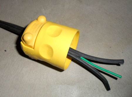
Picture: Wires Pulled Apart
After separated, insert the wires through the plug housing.
Step 5: Getting Wire Length Correct
Now you want to get wire length roughly correct. Upon inspecting the adapter it was easy to see that the wire length only needed to be as long as the plug housing.
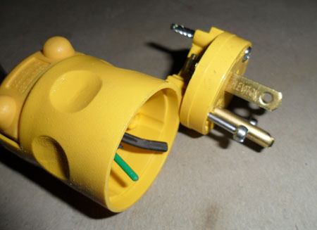
Picture: Sizing Up the Wire Length
As you can see above, the wires only need to be long enough to reach the top of the plug housing to reach the screw terminals.
Step 6: Wire It Up
Lets wire up the neutral, hot and ground wires.
Again, referring to the continuity test in Step 3, we'll just do a final sanity check by putting the plugs next to one another and looking where the textured wire would go on the new adapter. If you have a white wire that would correspond to the left prong on the plug. In my case it was the textured side of the wire that was verified as neutral in Step 3. This "neutral" wire gets hooked up to the silver screw (left prong).
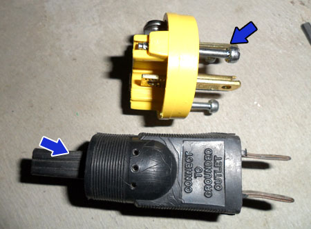
Picture: Plug Sanity Check. Textured wire goes to left prong (neutral).
You'll need to strip back the insulation on each wire. Approximately 0.25in should be good. If when you go to clamp the clamp goes down on the insulation, either strip the wire more or pull the wire back slightly. There should be enough wire for the clamp to be a good grip, but not too much that the bare wire is exposed far past the clamp.
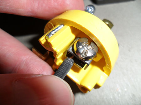
Picture: Insert Wire Into Clamp
Use the flat head screw driver to tighten the clamp. Make sure you really tighten it good, you don't want the wire to be loose in the clamp.
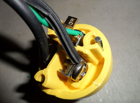
Picture: Completed Wiring
Pictured above is the final wiring. The plug is upside down but you can see that the textured "neutral" wire would go the the left prong (silver screw), the "hot" wire goes to the right prong (brass screw), and the green "ground" wire goes to the bottom prong (green screw). Your wires may be white for "neutral", black for "hot" and green for "ground" depending on the cord you are using.
Now we can reassemble the plug using a phillips head screwdriver..
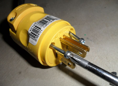
Picture: Reassembling the Plug
As pictured above, insert the blade end of the plug back into the plug housing and tighten the screws.
Finally tighten the clamp on the other end of the plug..
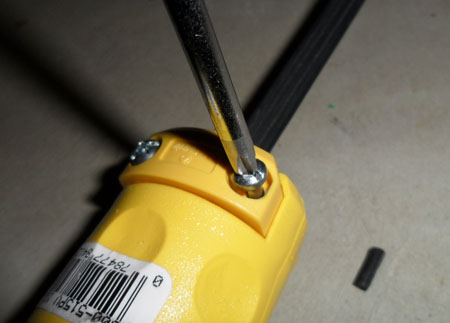
Picture: Tighten the Stress Relief Clamp
Finally, tighten the stress relieve clamp on the other end of the plug. You'll want to tighten this until it is snug on the insulation of the cord. Don't over-tighten, but in my case the cord is pretty flat and I had to tighten the screws very hard -- even switching over to a flat head screwdriver since the phillips head kept slipping.
That's it! All done with installing the new plug. Now we can test it out and see if it made a difference!
page1 page2 page3Comments:
No comments have yet been made.
